
Welding an UZI Receiver
|
|
Welding an UZI Receiver |
UZI Talk member suka5168 has done it again. First he built a Mini UZI and this time it's a full sized UZI built on a Group Industries receiver. The photos below should help anyone trying weld up an UZI receiver so it's ready for assembly.
An easy way to obtain all of the small parts needed to complete an UZI receiver is to buy a weld kit. Weld kits are still available from a few dealers for a little over $100 or you can demill them from an SMG parts kit. To weld a Group Industries receiver from a weld kit, lets begin with the basic weld kits itself.
|
There are 13 parts needed to complete a semi-auto UZI receiver: 1. Trunion (semi spec'd) 2. Front hand guard post (bayonet lug) 3. Trigger lug 4. Rear hand guard post 5. BOLT BLOCKING BAR (a must for any SEMI build) 6. Back plate 7. Feed ramp 8. Ejector 9. Ejector rivet 10. Rear sight base 11. Front sight base 12. Sling swivel 13. Sling rivet or washer
|
 |
|
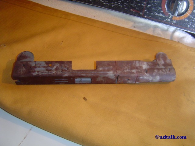
Here's a Group Industries receiver in the white.
Handling or humidity will quickly rust the receiver. You can buy Group
Industries
receivers finished to various degrees from rough stamped to
ready to weld. This is a rough stamped receiver. Notice the
lip that holds the front of the grip frame has not been stamped into the
bottom of the receiver. Also, the top edges of the receiver are not finished
and thus the top cover will not fit. For this article I will not go into how
to mill the rough stamped receiver into specs. The ready to weld receivers
are higher priced but will save you quite a bit of work.
|
 |
|
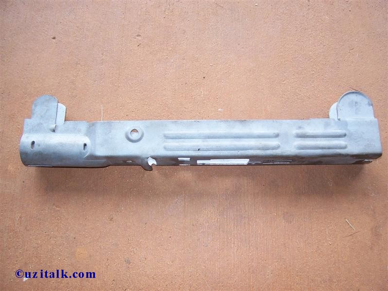
This ready to weld receiver has the proper "tabs" milled into the top of the receiver for the top cover to rest on.
|
 |
|
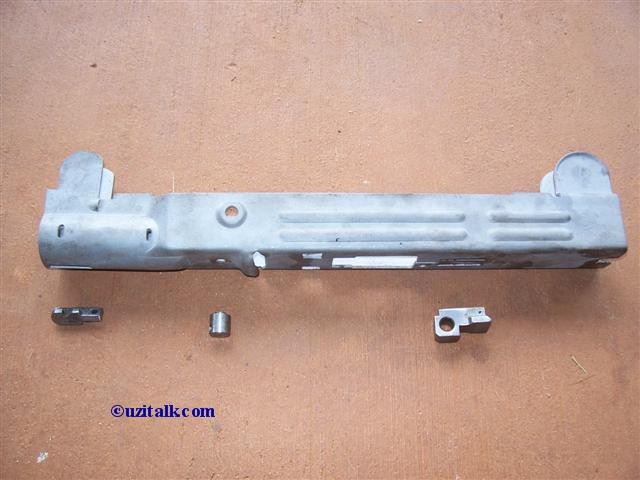
The first welds to be done are the three lugs on the bottom of the receiver - the bayonet lug (which also serves as the front hand guard post), the rear hand guard post, and the grip frame lug.
The grip frame lugs are available with two different sized holes - 8mm
or 9mm. The IMI semi-auto UZI used a 9mm lug, but if you're going to use a
surplus grip frame from an SMG, it's easier to use an 8mm lug, which is
what's used here.
|
 |
|
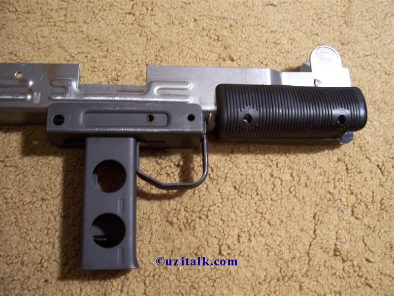
Using the hand guards and grip frame from an SMG parts kit, secure the pieces and do a dry fit to get a quick and accurate alignment without having to do any measuring or guess work. Do a quick spot weld and then remove the hand guards and grip frame.
|
 |
|
Weld the grip frame lug. |
 |
|
Weld the rear hand guard post and the bayonet lug.
|
 |
|
A bolt blocking bar MUST be welded in to make it a legal semi-auto UZI. To weld the blocking bar into the receiver, use the bolt as a guide. Place a few layers of tape under the bar and eyeball a even amount of space on the top, side and bottom of the bolt to give sufficient clearance. Do a quick spot weld and recheck the clearance. The bolt must move the entire course of the receiver freely. Proceed with the aid of a C clamp and weld all three holes along the right side of the receiver.
|
 |
| Make sure to leave enough clearance for the rear plate to go on by recessing the bar into the receiver by about 1/16"- 1/8" |
 |
|
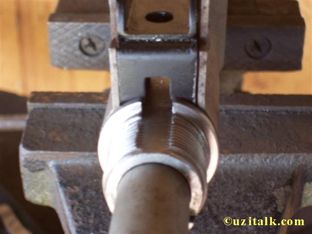
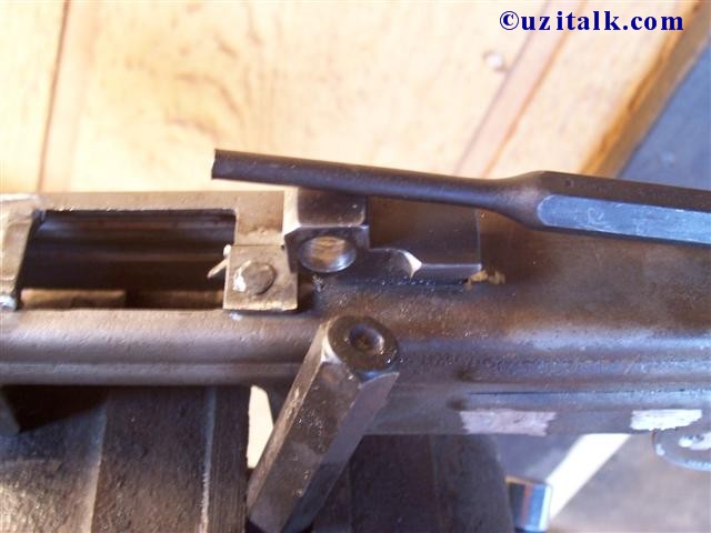
The trunion, feed ramp, and back plate are now ready to be installed. Some
parts suppliers can provide an alignment bar and rear plate jig (made from
brass) to properly align the trunion and feed ramp. Improper alignment can
cause feeding problems. Notice the rear plate jig has its centering hole
significantly lower than the actual rear plate to compensate for spec issues
with the Group Industries receivers. If an alignment bar is not available ,
one could be made from an UZI barrel. The close up picture shows the barrel inserted into the feed ramp. It should extend 1/32 - 1/16 beyond the ring. This ensures a chambered round will meet up with the bolt face. A bead of weld around the corners of the back plate in the form of an "U" is made. (not pictured)
|
 |
|
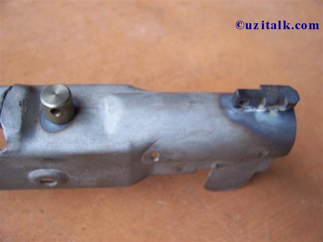
Use the front site base to make sure
the trunion is properly rotated before welding it. If the trunion is not
rotated properly, you won't be able to insert the barrel nut catch. At this time mark the front site base position relative to the receiver sight ears. If you're not using a spot welder as originally used by IMI, you'll need to drill a few holes in the side of the receiver to weld in the front sight base later on.
|
 |
|
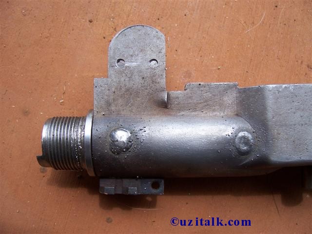
The two slots on each side of the receiver are to weld the trunion in place. Make the welds strong, allowing extra heat transfer and deep penetration. Failure of this weld can result in the EJECTION of the trunion and barrel during live fire. On the underside of the feed ramp place 2 weld along the sides. With your sight ears marked from the previous step, drill two small hole on each side of the receiver.
|
 |
|
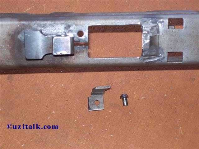
With the feed ramp and
grip frame lug welded, the ejector and rivet can be installed. |
 |
|
With a simple hammer and punch, the rivet can be bashed to a nice shape. An additional larger punch was drill to a round rivet head shape (as seen in the picture). The rivet head is 7mm at max width |
 |
|
The rivet head is as good as a factory
IMI production line. Function test the gun with the grip frame, magazine, barrel, and bolt installed. The bolt should move freely, loading should be smooth, and the rounds should extract and eject strongly. This particular build is a .40S&W UZI with the new .40S&W magazines and barrel by Barrelxchange.
|
 |
|
The rear sight is done in the same
manner as the front. Mark and predrill the 4 holes if using a MIG/TIG
welder. Dry fit the rear sight base with the aid of the top cover and cover catch. This should give a good estimate of the position. The top cover and rear sight base should sit flush with each other and the cover catch should slide freely between the two. Also, the bolt should freely move under the rear sight base. This photo shows the rear receiver plate welds prior to being cleaned up. Drilling the center sight screw is rather a precise task. Taking the measurement from a IMI SMG and a completed Group Industries receiver, the average of the two came to:
ends of ear to center 18.5 mm
|
 |
|
Making sure the barrel nut catch has
enough clearance and slides freely in the slot, the front sight base can be
welded in place. The front vertical corners of the base are also welded.
Grind off the excess protrusions and edge the corners to a nice round shape.
|
 |
|
All welding is now complete and the
receiver can be deburred with a wire brush and rough areas ground smooth. A
quick media blast also cleaned up most of the surface rust and splatters.
|
 |
|
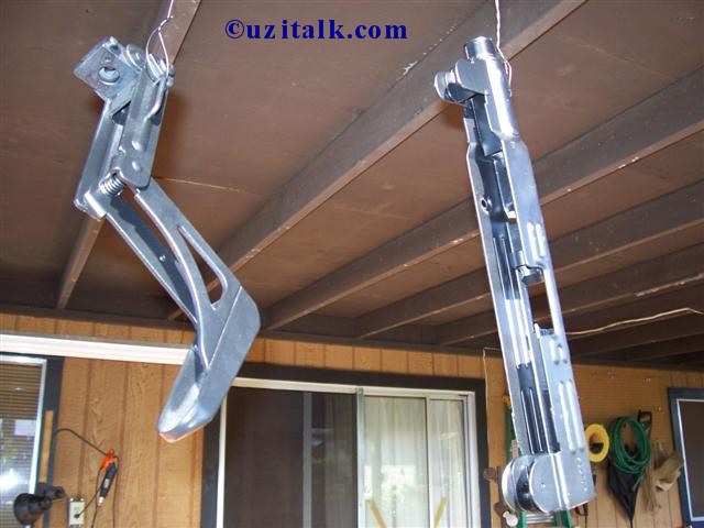
With the surface prep'd,
both receiver & stock got a fresh coat of paint. |
 |
|
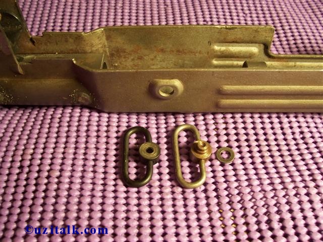
After allowing the paint to dry, the final step to complete a 100% receiver is the installation of the sling swivel. Two types of swivels are available. Original IMI are in black, whereas the silver ones are US made. Installation is rather different for each type of swivel. IMI's require an additional rivet, compared to a washer for the US swivels.
|
 |
|
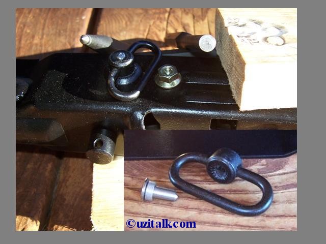
I chose to use an IMI swivel from a parts kit. The rivet was drilled out of this IMI sling swivel in the demilling process and a new rivet is used. (pictured is a scrap pin). Place the rivet from inside the receiver channel, cap the rivet with the swivel. With the aid of a nut and some wood scraps, tap down on the swivel. Punches are used to flare the ends of the rivet. A light coat of paint was sprayed
over the area after completion.
|
 |
|
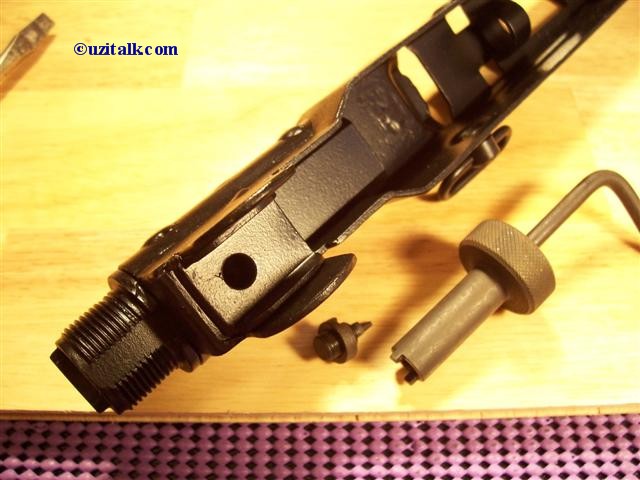
The receiver is now done and assembly of the gun can begin. Installation of a semi buffer is done after the stock is installed. The side of the buffer with fewer holes faces the rear. (facing the stock) The insert picture (lower right) shows the front of the buffer after installation. |
 |
|
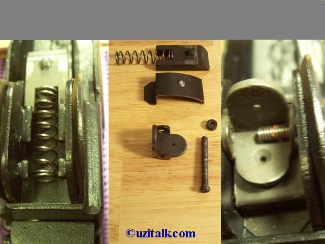
The rear sight for a Model
"A" consists of six different parts. Place the top cover catch as pictured
with the spring just inline with the small indentation. The leaf spring is
placed over the top of the cover catch so that with the flat portion of the
leaf spring is towards the back. Compress the cover catch spring by pushing
the cover catch back and clip the front of the leaf spring over it. |
 |
|
The model A front sight screws in easily with the aid of a sight tool. |
 |
|
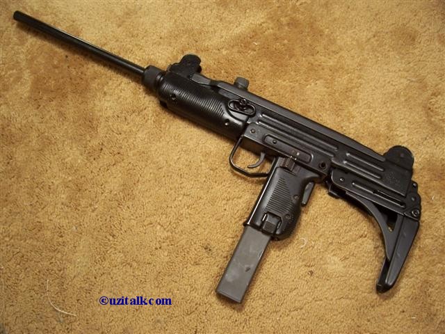
You can now assemble the
hand guards, lower assembly, top cover, barrel, and magazine. A working Semi
auto UZI is brought to life! |
 |
Copyright © 2002-2017, UZITalk.com
International copyright laws
DO apply to
Internet Web Sites!
All Rights Reserved.
Last Modified: May 27, 2017
Contact:
librarian@uzitalk.com